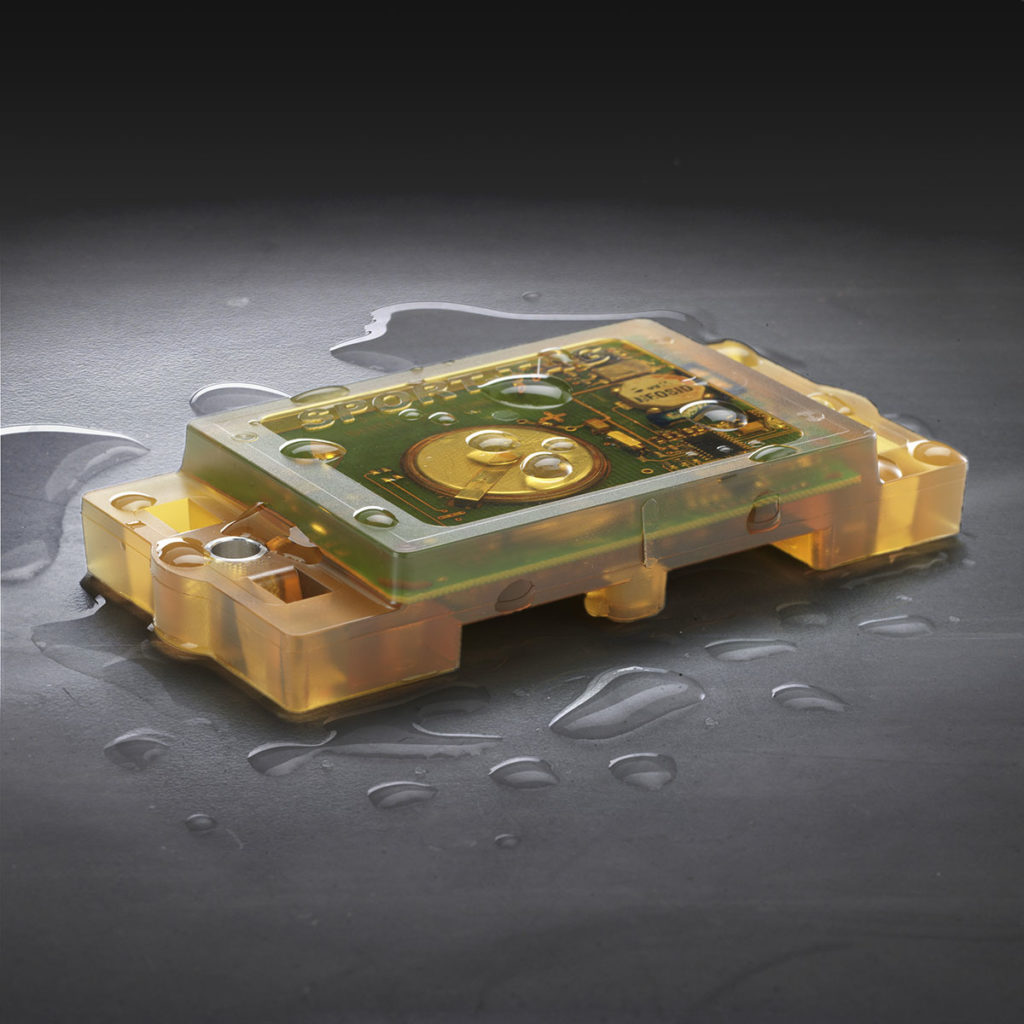
Customers frequently ask us how to design a part for low pressure molding (LPM). Over the years, Cavist has built a comprehensive set of guidelines we utilize to ensure our success. Most of this knowledge was derived from years upon years of making mistakes, but looking back there is some common sense that is involved. The subject is much deeper than what can be conveyed in an article; but there are a few basic design guidelines and considerations worth sharing.
The first bit of design advice seems quite intuitive and is as old as any engineering principle: know what you are up against. This adage is what led us to the development of our application checklist over 20 years ago. The way we approach an overmold is heavily dependent upon the requirements of the end-use environment. We will not approach the design of an indoor strain relief application the same way we would approach the design of an overmolded automotive sensor. This seems intuitive, at first glance, but knowing exactly what you want from the design is the first place to begin. Do you require an IP67 level of protection, or is it IP65? The two requirements demand completely different molding solutions. Will there be any level of UV exposure or solvents of any kind? These considerations impact not only the overmold design itself, but the material considerations. Begin any LPM design with a thorough understanding of the end use environment, and all testing requirements. From there, a material candidate can be selected, and you can move into the various design tradeoffs.
Below is a sequence of images illustrating a typical 2-Step encapsulation using low pressure molding materials.
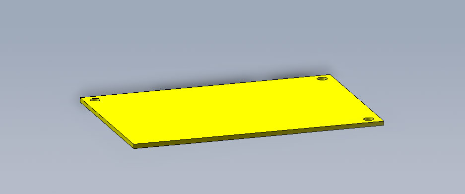
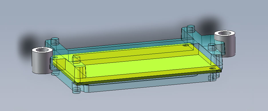
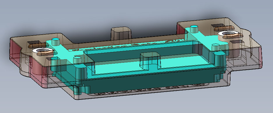
After determining the project goals, the next step is to assess whether the overmold should be done in one or two molding steps. In a single-step molding approach, there will be points of exposure in the final overmold. The moldset must contact the device somewhere to ensure proper alignment in the cavity. If the tool is contacting the electronic assembly during the mold cycle, a complete encapsulation is not possible without shooting a second shot. Most designs requiring a high level of ingress protection demand a two-step overmolding approach. There are ways to achieve aggressive ingress protection in a single shot, but you must pay careful attention to any potential leakage path. A leakage path is any part of the assembly that protrudes through the overmold envelope. This could be a wire exiting the overmold, a connector shut-off, a push button switch, or any exposed PCB surface or component. All leak paths provide an opportunity for failure and should be approached as such. Knowing the possible leak paths in a molded assembly, you can decide how to index the electronics in the moldset for the first shot, and then determine if a second molding step is necessary.
The next step in designing for LPM is to decide on the proper orientation of the part in the tool cavity. This not only dictates the parting line, but also has major impacts on manufacturability and cycle time. There may be an obvious choice for a parting line, but one orientation may result in a molded part that is very hard to remove without ejectors. Alternatively, there may be a tendency for parts to remain stuck to the upper mold half when the mold opens. The molded assembly may have wires, compression limiters or hand-loads, which should be close to the operator, rather than the machine. All of these design choices impact how the operator, or robot, will interface with the manufacturing setup, and ultimately affect tool design, cycle time and production scrap rates.
The final LPM design guidelines are the very basic bits of information that probably led you to begin reading this article in the first place. Things like max and min skin thickness, draft, material shrinkage and sink in the final molded product, etc. As a rule of thumb, any skin thickness that must be flowed with high repeatability should be no thinner than 1.0 mm. We have production parts with skin thicknesses below this, but there is always a risk of material freezing off and/or short shots. On the maximum side, any section thickness greater than 6 mm will be prone to shrinkage, which presents itself as sink in the finished product. In general LPM materials have a linear shrinkage rate of 1.5%, which sounds significant, but in most cases it is negligible. Consider the fact that the electronics will only allow the overmold material to contract in certain areas. If the skin thickness is only 1-2 mm, the 1.5% average shrinkage will be unimportant.
The guidelines put forth in this article are, by no means, comprehensive or a ticket to a successful overmold design. They should set out some basic considerations and a place to start the discussion. If you are considering an overmold design, let our years of expertise take your project from ‘Vision to Volume’.
